There are 2 main ways of output for metal frames from CAD engineer point of view. I am not talking about whether to use CAD software frame generators or not here. That should be basic skill :)
One option gives opportunity to get precisely cut parts from re-seller pipe laser and other one is faster to make with CAD software. Witch one should be used and when then ?
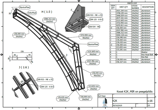
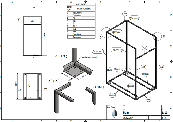
The first and more simple way is to make assembly drawing of the framework and show all its holes and other works on that one. I personally always add BOM with all quantities, pipe length and size. By doing this all info is on the drawing without going into naming individual parts.
Advantage with this is speed and that whole output is just single PDF file. The downside is that all holes must be drilled by hand, pipes must be saw by hand and so on.
The other option is having parts named and then exported individually into different .step files. That gives huge advantage because then all pipes can be cut into size with all the desired holes and shapes already at the material re-seller with pipe laser. Not only it is basically almost free it gives advantage to have very precise holes and cutouts.
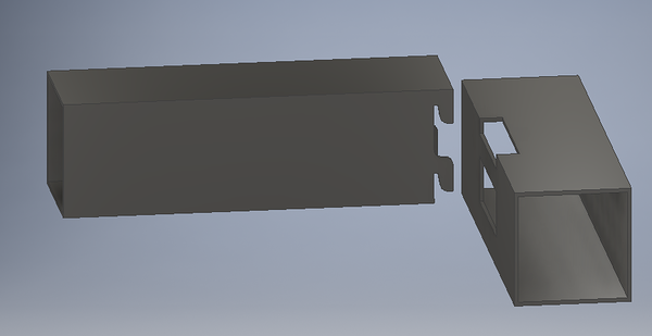
For example this selftightening connection I have been using for years. It also gives advantage to bring wires trough inside of the pipe. To open it must use rubber hammer:
For conclusion the way to go must be chosen by what kind of work is being done. If the frame is simple, does not need precise holes and quantity is 1 or 2 then go with first option, if not choose the second one.


77 replies